

Outline
The equation used in the calculation of pressure loss in piping is called Fanning's equation. This is expressed by Eq. (1).
$$ΔP=4f\frac{ρu^{2}}{2}\frac{L}{d}・・・(1)$$
where ΔP is the pressure drop, f is the friction coefficient, ρ is the liquid density, u is the liquid velocity, L is the pipe length, d is the pipe diameter.
Fanning's equation is used to calculate the pressure drop in a straight pipe when calculating the pump head.
The friction loss hydraulic head hf, explained in the article on Bernoulli's theorem, can be calculated from the pressure drop ΔP in Fanning's equation.
$$h_{f}=\frac{ΔP}{ρg}・・・(2)$$
Eq. (2) allows us to convert from ΔP (pressure) to hf head (length) units.
If the pump head is determined only by the actual head without considering the pressure drop in Fanning's equation, the pump will not be able to transfer the fluid to the desired location because of the loss of energy due to friction between the fluid and the piping.
Therefore, it is necessary to calculate the pressure drop properly and add the energy loss due to friction to determine the pump head.
Derivation of Fanning's equation
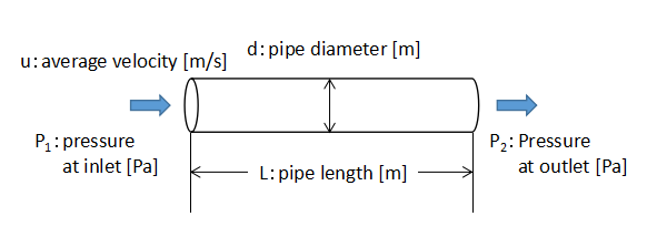
Consider the pipe flow shown in the above figure.
Assume that the fluid is flowing through the pipe with an average velocity u.
At this point, the fluid exerts a force F on the wall due to its viscosity. This force F is expressed by Eq. (3) with the friction coefficient f as a constant.
$$F=f・(πdL)・\frac{1}{2}ρu^{2}・・・(3)$$
The loss of force FL due to pressure drop in the section of pipe length L is given by Eq. (4).
$$F_{L}=\frac{πd^{2}}{4}(P_{1}-P_{2})=\frac{πd^{2}}{4}ΔP・・・(4)$$
Since the force F exerted by the fluid on the wall and the force loss FL in this section are equal, Eq. (3) = Eq. (4).
$$f・(πdL)・\frac{1}{2}ρu^{2}=\frac{πd^{2}}{4}ΔP$$
$$ΔP=4f\frac{ρu^{2}}{2}\frac{L}{d}・・・(1)$$
Transforming the equation into Eq. (1) at the beginning of this section, we were able to derive Fanning's equation.
Use of different coefficients of friction f
In practice, it is important to know what value of the friction coefficient f to calculate.
We can imagine that the friction coefficient f, which represents the degree of friction of a fluid, varies depending on the flow conditions (laminar flow, turbulent flow) and the roughness of the pipe wall.
Therefore, equations for determining the coefficient of friction under various conditions have been published.
Among them, the following two equations are the easiest to calculate.
・Laminar flow (Re≦2,000)
$$f=\frac{16}{Re}$$
・Turbulent flow (3,000≦Re≦100,000)
$$f=0.0791Re^{-0.25}$$
Another method is to read and use the value of the coefficient of friction from the Moody chart, which plots the results of various experiments on the coefficient of friction.
The below figure shows the Moody chart.
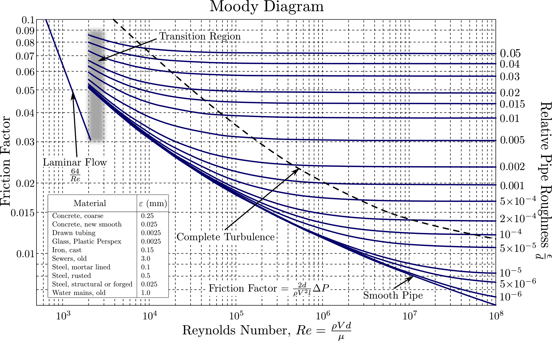
Quoting from "https://en.wikipedia.org/wiki/Moody_chart"
However, it is important to note that Moody diagrams are often used in the field of mechanical engineering, where λ, not the friction coefficient f, is plotted on the vertical axis.
In the field of mechanical engineering, the Darcy-Weisbach equation exists with a similar meaning to Fanning's equation.
$$h_{f}=\frac{ΔP}{ρg}=λ\frac{u^{2}}{2g}\frac{L}{d}・・・(5)$$
Eq. (5) is the Darcy-Weisbach equation.
Substituting Fanning's Eq. (1) into Eq. (2), we get Eq. (6), which is almost the same form as Eq. (5).
$$h_{f}=4f\frac{u^{2}}{2g}\frac{L}{d}・・・(6)$$
Comparing Eq. (5) with Eq. (6), we get Eq. (7).
$$λ=4f・・・(7)$$
Therefore, by dividing λ read from the Moody diagram by 4 we get the friction factor f. Don't forget to convert it.