

Outline
The energy conservation law for fluids is called Bernoulli's principle in particular.
Bernoulli's principle for a perfect fluid without compressibility and viscosity is expressed by Eq. (1).
$$\frac{v_{2}^{2}-v_{1}^{2}}{2}+g(z_{2}-z_{1})+\frac{P_{2}-P_{1}}{ρ}=0・・・(1)$$
The first term represents kinetic energy, the second term represents potential energy, the third term represents pressure, and the energy of the fluid is the sum of these terms.
It also means that kinetic energy and pressure can be converted into potential energy. This has very important industrial implications.
Because it shows that you can lift a fluid to a higher level if you pump it to a higher pressure.
Due to the location constraints, plants are often structured to be long and vertical structures.
Equipment such as heat exchangers, distillation columns, and agitation vessels may be installed high up in the structure, so it is necessary to transport the fluid to them.
Thanks to Bernoulli's principle, engineers can calculate how much energy and pump lift is needed to lift a fluid to a given height.
Derivation of Bernoulli's Principle
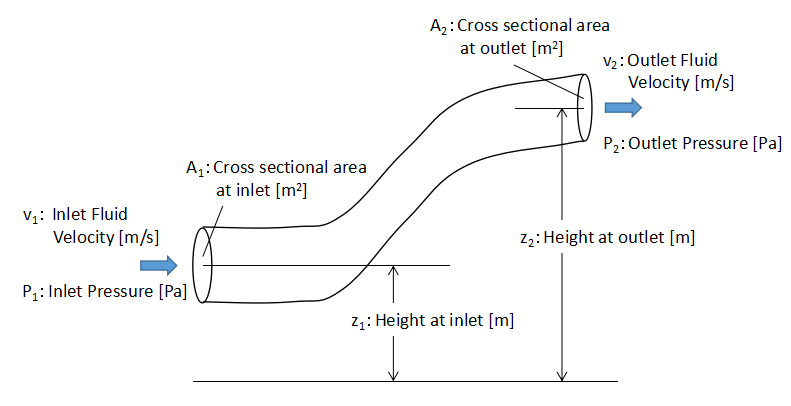
We take the energy balance of the flow in the flow pipe as shown in the above figure.
Assuming that the fluid is a perfect fluid, the energy loss associated with the flow can be neglected.
Here, we consider each energy (kinetic energy, potential energy, and pressure) at the inlet and outlet of the flow pipe.
In the physics of rigid bodies, each energy is Eq. (2)-(4).
$$Kinetic\ Energy=\frac{1}{2}mv^{2}・・・(2)$$
$$Potential\ Energy=mgz・・・(3)$$
$$Work\ by\ pressure (force\ ・\ distance)=PA・x・・・(4)$$
where m is the mass of a substance, v is the velocity of a substance, g is the gravitational acceleration, z is location of a substance, P is pressure, A is Area where the force acts, x is travel distance.
The units of each equation are kg・m2/s2 = N・m = J (Joule).
Basically, if we apply Eq. (2) to (4) to the fluid and take the energy balance at the inlet and outlet, we get the form of Bernoulli's principle.
First of all, the mass of the fluid is expressed by the following equation.
$$ρFdt$$
where ρ is the fluid density, F is the volume flow rate , and dt is the fluid flow time in a very short time.
The volume flow rate F can be expressed as the cross-sectional area of the section A and the flow velocity v.
$$F=Av$$
The distance x traveled by the fluid is given by the flow velocity v and the time dt of fluid flow.
$$x=vdt$$
Based on the above relationship, if the energy at the inlet of the flow pipe and the energy at the outlet are conserved and equal, then Eq. (5) holds.
$$\begin{align}&\frac{1}{2}ρF_{1}dtv_{1}^{2}+ρF_{1}dt・g・z_{1}+P_{1}A_{1}・v_{1}dt\\&=\frac{1}{2}ρF_{2}dtv_{2}^{2}+ρF_{2}dt・g・z_{2}+P_{2}A_{2}・v_{2}dt・・・(5)\end{align}$$
The left side at Eq.(5) shows the energy at the inlet of the flow pipe and the right side shows the energy at the outlet of the flow pipe.
Assuming that the fluid is always flowing continuously, Eq. (6) holds because the volume flow rate F is equal at all locations.
$$F_{1}=F_{2}=v_{1}A_{1}=v_{2}A_{2}・・・(6)$$
Converting the volume flow rate F in Eq. (5) to v1A1 in Eq. (6) and dividing both sides of Eq. (5) by ρv1A1dt, Eq. (7) is formed.
$$\begin{align}&\frac{1}{2}v_{1}^{2}+gz_{1}+\frac{P_{1}}{ρ}\\&=\frac{1}{2}v_{2}^{2}+gz_{2}+\frac{P_{2}}{ρ}・・・(7)\end{align}$$
If we put the form right side - left side = 0, we get Eq. (1), and Bernoulli's principle can be derived.
$$\frac{v_{2}^{2}-v_{1}^{2}}{2}+g(z_{2}-z_{1})+\frac{P_{2}-P_{1}}{ρ}=0・・・(1)$$
By the way, if you divide both sides of Eq. (7) by the gravitational acceleration g, the unit system of the equation becomes m (meter).
$$\frac{v_{1}^{2}}{2g}+z_{1}+\frac{P_{1}}{ρg}=\frac{v_{2}^{2}}{2g}+z_{2}+\frac{P_{2}}{ρg}$$
In this case, the total energy hydraulic head H is expressed by Eq. (8).
$$H=\frac{v^{2}}{2g}+z+\frac{P}{ρg}=constant・・・(8)$$
Eq. (8) is the base equation when calculating the pump head.
Each term in the equation is referred to as
$$Velocity\ Head:\frac{v^{2}}{2g}$$
$$Positional\ Head:z$$
$$Pressure\ Head:\frac{P}{ρg}$$
Extension to real viscous fluids
Eq. (1) and (8) are valid for perfect fluids, which are fluids in which viscosity does not work.
However, because of the viscous nature of real world fluids, energy loss due to friction, etc. occurs.
So, in order to apply Eq. (8) to a real fluid, we add two terms to Eq. (8) to represent the energy loss.
$$H=\frac{v^{2}}{2g}+z+\frac{P}{ρg}+h_{f}+h_{l}・・・(9)$$
Eq. (9) is used in practice to calculate the pump head.
The hf is called the frictional loss hydraulic head and represents the energy loss due to friction on the pipe wall.
The hl is called the shape loss hydraulic head, and it represents the energy loss that occurs at points where the flow path changes significantly, such as at a sudden expansion or contraction of the pipe or at a bend.
Therefore, when calculating the head of the pump, it is necessary to determine the head by adding the energy loss according to Eq. (9).