

Outline
When a fluid loses energy due to friction with a wall or between fluids, it is called pressure loss.
When a fluid is pumped to move with energy, Bernoulli's theorem is theoretically true.
However, in reality, pressure loss occurs, the lost energy must be added to the fluid.
Therefore, it is very important to calculate and estimate the pressure drop.
In this article, we will introduce a calculation method for pressure loss in a piping flow path, which is frequently calculated in practice.
How to calculate pressure loss
Straight pipe
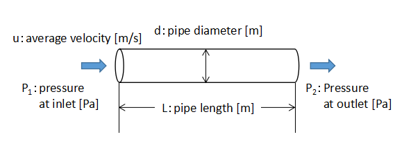
The pressure drop in a straight pipe can be calculated using Fanning's equation.
-
Fanning's equation:Pressure drop in piping
Fanning's equation is used to calculate the pressure drop in a straight pipe when calculating the pump head. If the pump head is determined only by the actual head without considering the pressure drop in Fanning's equation, the pump will not be able to transfer the fluid to the desired location because of the loss of energy due to friction between the fluid and the piping.
続きを見る
Eq. (1) is Fanning's equation.
$$ΔP=4f\frac{ρu^{2}}{2}\frac{L}{d}・・・(1)$$
where ΔP is the pressure drop, f is the friction coefficient, ρ is the liquid density, u is the liquid velocity, L is the pipe length, d is the pipe diameter.
When calculating the pump head in head [m], use Eq. (2), where both sides of Eq. (1) are divided by ρg.
$$h_{f}=4f\frac{u^{2}}{2g}\frac{L}{d}・・・(2)$$
where hf is the friction loss hydraulic head.
Special shape of piping flow path
Piping does not consist of only straight pipes, but actually has variously shaped flow paths in between, such as bends, expansion and contraction sections, valves, etc.
The loss head due to these specially shaped sections is called the shape loss hydraulic head hl[m].
$$h_{l}=f_{l}\frac{u_{m}^{2}}{2g}・・・(3)$$
The shape loss hydraulic head hl is basically expressed in the form of Eq. (3).
Since the value of the coefficient of friction fl varies depending on the shape, we have to find the coefficient of friction fl for each shape.
Loss head from rapid expansion
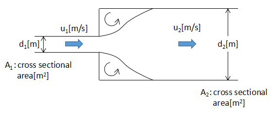
When the channel expands rapidly, vortices are formed in the rapidly expanding area because the flow cannot immediately follow the channel shape.
This vortex is a flow that stays in place, and for the purpose of delivering the fluid to its designated location, it is clearly a waste of energy and a loss.
The rapid expansion loss head hse[m] is expressed by Eq. (4) and (5).
$$h_{se}=f_{se}\frac{u_{1}^{2}}{2g}・・・(4)$$
$$f_{se}=(1-\frac{A_{1}}{A_{2}})^{2}=[(1-(\frac{d_{1}}{d_{2}})^{2})]^{2}・・・(5)$$
where fse is the rapid expansion loss coefficient, um is the average flow rate in the pipe, g is the gravitational acceleration.
Loss head from rapid reduction
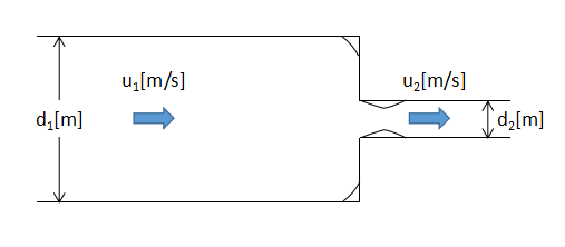
When the flow path shrinks rapidly, vortices are generated in the rapidly shrinking part and energy is lost as well.
The loss head hsc[m] due to the steep reduction is expressed by Eq. (6) and (7).
$$h_{sc}=f_{sc}\frac{u_{2}^{2}}{2g}・・・(6)$$
$$f_{sc}=(\frac{1}{C_{c}}-1)^{2}・・・(7)$$
where fsc is the shrinkage loss coefficient, Cc is the reduced flow coefficient.
The reduced flow coefficient Cc cannot be determined theoretically, but must be referred to experimental values.
In some reference books, the reduced flow coefficient Cc itself is given, or the rapid shrinkage loss coefficient fsc is given directly.
The below table shows the rapid shrinkage loss coefficient fsc for the pipe shrinkage ratio d2/d1.
| d2/d1 | rapid shrinkage loss coefficient fsc |
| 0 | 0.50 |
| 0.1 | 0.50 |
| 0.2 | 0.49 |
| 0.3 | 0.49 |
| 0.4 | 0.46 |
| 0.5 | 0.43 |
| 0.6 | 0.38 |
| 0.7 | 0.29 |
| 0.8 | 0.18 |
| 0.9 | 0.07 |
| 1.0 | 0 |
Inlet loss head
Inlet loss head occurs when fluid flows from a large tank into a narrow pipe.
The inlet loss hydraulic head he[m] is Eq. (8).
$$h_{e}=f_{e}\frac{u_{m}^{2}}{2g}・・・(8)$$
where fe is the inlet loss coefficient.
The inlet loss head fe varies depending on the inlet shape.
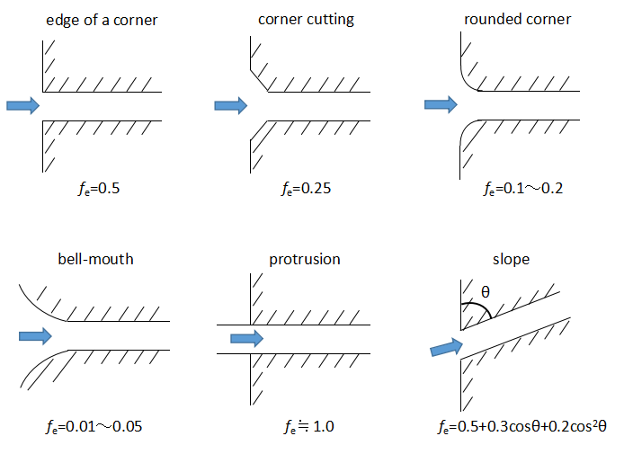
The above figure shows a typical inlet shape and the values of inlet loss head fe.
Outlet loss head
When a fluid flows out of a narrow pipe into a large tank, an outlet loss head is generated.
The outlet loss head ho[m] is given by Eq. (9).
$$h_{o}=f_{o}\frac{u_{1}^{2}}{2g}・・・(9)$$
where fo is the outlet loss coefficient.
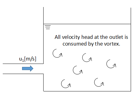
For example, in the case of a discharge into a tank, all the velocity head at the outlet of the channel is consumed by forming a vortex in the tank.
Therefore, an outlet loss factor fo of 1 is often used and it is assumed that the velocity head is consumed at the outlet of the channel.
Loss head from gradual expansion
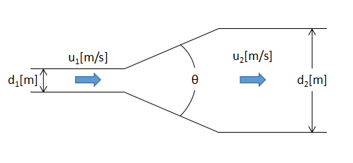
In a gradually expanding flow path, energy is lost due to eddies caused by flow separation, although not as much as in a rapidly expanding flow path.
The gradual loss hydraulic head hge[m] is given by Eq. (10).
$$h_{ge}=f_{ge}f_{se}\frac{u_{1}^{2}}{2g}・・・(10)$$
where fge is the gradual expansion loss coefficient, fse is the rapid expansion loss coefficient.
Since the gradual expansion loss coefficient fge varies with angle θ, read and use the value from the below figure.
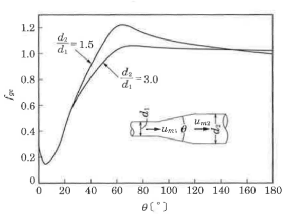
Quoting from "水理学の基礎"
Loss head from gradual reduction
Since there is almost no energy loss in a gradually shrinking flow path, it can be ignored in the pressure drop calculation.
Loss head due to curved pipes and valves
The simplest way to determine the pressure loss of a curved pipe and valve is to calculate the straight pipe equivalent length Le[m] and use Fanning's equation.
Various experiments have been conducted in the past, and each reference book shows how much the pressure loss for each shape can be converted to a straight pipe.
$$L_{e}=n・d・・・(11)$$
where n is the coefficient, d is the pipe diameter.
The straight pipe equivalent length Le[m] can be calculated using Eq. (11).
Typical coefficients n are shown in the below table.
| Pipe inserts | n |
| 45° elbow | 15 |
| 90°elbow(Standard curvature) | 32 |
| 90°bend(Curvature/Diameter=3) | 24 |
| 90°bend(Curvature/Diameter=4) | 10 |
| 180°bend | 75 |
| Cross-joint | 50 |
| T-joint | 40~80 |
| Gate valve(fully open) | 0.7 |
| Gate valve(1/4 closed) | 10~40 |
| Gate valve(1/2 closed) | 100~200 |
| Gate valve(3/4 closed) | 800 |
| Globe valve(fully open) | 300 |
| Angle valve(fully open) | 170 |
| Hydrometer(piston type) | 600 |
| Hydrometer(disk type) | 135~400 |
| Hydrometer(winged turbine type) | 200~300 |
| union | 0 |
| coupling | 0 |